
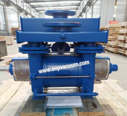
Liquid Ring Compressor in Flash Steam Recovery on Offshore Platforms
In order to recover low-pressure natural gas generated by the secondary separator and reduce torch gas emissions, a liquid ring compressor was first used for low-pressure flash gas recovery and reuse on an offshore platform. Compared with conventional screw and reciprocating compressors, the liquid ring compressor has advantages such as small temperature rise, fewer maintenance components, and small footprint, especially suitable for compact offshore oil production platforms.
1. Analysis of compressor selection
Reciprocating compressors, screw compressors, and liquid ring compressors are mainly used in low-pressure flash steam recovery. Among them, screw and liquid ring compressors have a wide range of applications. In onshore oil and gas fields and the petrochemical industry, with the production and sales of liquid ring compressors in China, the proportion of adoption is increasing.
A comparative analysis of the three compressors is shown in the table below.
Table 1 Comparison of Three Types of Compressor Selection
| Comparison Content | reciprocating compressor | screw compressor | liquid ring compressor |
| Processing capacity and pressure range | Suitable for small and medium-sized gas flow, with a wide range of pressure, especially suitable for high and ultra-high pressure | Suitable for small and medium-sized gas flow, with a maximum single stage compression pressure of about 600~700kPaG, and a wide pressure range | Suitable for small and medium-sized gas flow, with a maximum single stage compression pressure of about 600~800kPaG, and a wide pressure range |
| Characteristics of compression form | Approaching adiabatic compression, the temperature rise is affected by the compression ratio, and the temperature is relatively high, making the unit prone to coking | Approaching adiabatic compression, with a temperature rise of around 70 ℃, the unit is prone to coking | Almost isothermal compression, maximum temperature rise not exceeding 10 ℃, no risk of coking |
| Component materials and characteristics | The components are made of carbon steel, which cannot solve the material corrosion problem for sulfur and corrosive gases. | The components are made of carbon steel and are cooled and lubricated using a medium containing liquid, which cannot solve the problem of material corrosion for sulfur-containing and corrosive gases. | Multiple materials available. Generally, dual phase steel is used, with basic isothermal compression inside, which can effectively solve problems such as corrosion of sulfur-containing and corrosive gases, as well as medium and environment pollution caused by lubricating oil. |
| Compressor components, structure, and maintenance characteristics | There are many components that generally require on-site adjustment during final assembly. Vulnerable parts are frequently replaced, resulting in a large disassembly workload and difficult maintenance. | There are many components and the structure is particularly complex, making it difficult to replace them. In general, if a rotor malfunctions, it needs to be returned to the factory for repair, which is difficult to assemble and requires high assembly accuracy. | The compressor has fewer components and a simple structure. Due to no substantial contact wear, component replacement is simple and easy to operate, and the assembly workload is small, with low requirements for assembly accuracy. |
| unit efficiency | The unit has contact wear, and after running for a period of time, the gap between the unit components increases, the compression and exhaust capacity decreases, efficiency decreases, and energy consumption increases. | No contact wear, constant efficiency, constant energy consumption, and stable performance | |
| Noise and vibration | Unbalanced inertial force, high vibration, and high noise | Good power balance and low vibration | The vibration and noise of the exhaust are relatively small |
| Volume, weight | The inlet is equipped with equipment such as a liquid separation tank, which has a larger pry size and a heavier weight | Compared to liquid ring compressors, they have a larger footprint and weight. | Compact structure, small size, and relatively light weight |
| Media requirements | Not applicable for water containing, sulfur containing or corrosive gases, particulate gases | Suitable for aqueous media, but not for sulfur-containing or corrosive gases, particulate gases | Fully applicable for water containing, sulfur containing or corrosive gases, particulate gases |
2. Offshore application of liquid ring compressors
Taking the low-pressure flash steam of a certain offshore center processing platform as an example, the natural gas composition and inlet conditions are shown in Table 2 below. The flash steam inlet temperature is 100 ℃, and the inlet pressure is 50kPaG. After compression, the pry edge outlet temperature is required to be 40 ℃, and the outlet pressure is 350kPaG.
Table 2
| CO2 | CH4 | C2H6 | C3H8 | i-C4H10 | n-C4H10 |
| 0.0041 | 0.1776 | 0.0279 | 0.032 | 0.0077 | 0.0191 |
| i-C5H12 | n-C5H12 | n-C6H14 | n-C7H16 | C7+ | H2O |
| 0.0066 | 0.0045 | 0.0063 | 0.0085 | 0.033 | 0.6727 |
And suitable for circulation, the gas phase after dehydration enters the downstream production system. Based on the comparative analysis of compressor selection, a liquid ring compressor oil phase is used to enter the closed discharge system. By controlling the circulating liquid flow rate to achieve pressure for flash steam recovery, a steady-state compression process is established through simulation, and the compressor return flow rate is determined to meet the outlet temperature requirement of 40 ℃ at the compressor outlet. The compressor inlet and outlet temperature is approximately the indicator requirement. About 3 ℃, with a small temperature rise.
The process flow is shown below. The flash steam first enters the inlet cooler and cools to 45 ℃. After mixing with the circulating liquid, the temperature decreases to about 37 ℃. Then, it enters the liquid ring compressor and is compressed to 350kPaG before entering the outlet separator for liquid removal. The separator is a three-phase separator, and the separated water phase is used as the circulating liquid to enter the circulating cooler. After cooling to 35 ℃, it is used as the compressor coolant. According to process simulation and considering a certain design coefficient, The equipment parameters are determined in the table below.
Table 3 Design parameters of equipment inside the liquid ring compressor skid
| Device Name | Inlet cooler | liquid ring compressor | Outlet separator | Circulating liquid cooler |
| design capacity | 850kW | 750Sm3/h(gas)16.5m3/ h(liquid) | 750Sm3/h(gas)17.3m3/ h(liquid) | 70kW |
| Operating pressure/temperature | 50kPaG/100~45°C(flash steam side)
650kPaG/-1.6~29°C TO 8.4~39°C(Sea water side) |
20kPaG/36~37°C(Entrance)
350kPaG/40°C(exit) |
350kPaG/40°C | 350kPaG/40~35°C(flash steam side)
650kPaG/-1.6~29°C TO 8.4~39°C(Sea water side) |
| Design pressure/temperature | 1250kPaG/130℃ | / | 850kPaG/70°C | 1250kPaG/70℃ |
3. Conclusion
By comparing and analyzing the selection of commonly used low-pressure gas recovery compressors, it is found that liquid ring compressors have the characteristics of wide pressure range, low compression temperature rise, few maintenance components, simple maintenance, stable unit efficiency, small footprint, and light weight. For media, they can handle water and oil containing gases, and corrosive and particulate gases are also applicable. Therefore, liquid ring compressors are suitable for intensive offshore oil extraction platforms.