
Vacuum degassing equipment
Analysis and Research on excessive resistance drop of vacuum degassing unit
The possible causes of excessive resistance drop in the pumping system of vacuum degassing device are analyzed, and a calculation model suitable for engineering design is established. The calculation results show that the gas cooler is the main reason for excessive resistance drop, and the calculation results are close to the measured values of vacuum gauge. New improvement methods are proposed, such as increasing the conduction area of the cooler and adjusting the layout of the tube. Finally, a new type of cooler design scheme is presented, which reduces the resistance drop of the system from 200 Pa to 21 Pa, the working vacuum to more than 67 Pa, and the end point from 2.2 ppm to 1.4 ppm, so as to meet the requirements of metallurgical process.
vacuum degassing equipment schematic diagram
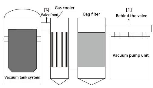
1. The schematic diagram of vacuum degassing equipment and vacuum degassing (VD) is one of the important means of refining molten steel outside the furnace. It means to remove harmful gases such as H and O in molten steel under certain vacuum environment and reduce the content of N to a lower range, which plays an important role in the production of high-quality alloy steel for iron and steel enterprises. Endpoint content is the main performance evaluation index of VD equipment. In order to meet the requirements of special steel grades, the content of molten steel after treatment is generally required to be less than 2 ppm. In order to obtain a better dehydrogenation rate, according to the relationship between solubility and vacuum degree obeying the quadratic root law, the working vacuum degree should be higher than 67 Pa, that is to say, only when the pressure in the vacuum tank is lower than 67 Pa, the dehydrogenation and deoxidation goals can be achieved. The object of this study is a new VD vacuum degassing device for a domestic user. Compared with traditional equipment, oil-free mechanical pump unit is adopted, which has low maintenance cost, more economical, energy-saving and environmental protection. The equipment is mainly composed of the following parts: mechanical pump system, dust removal system and vacuum tank system, as shown in Figure 1. The mechanical vauum pump unit is composed of screw vacuum pump and Roots vauum pump. The dust removal system consists of gas cooler and bag filter. The vacuum tank system consists of vacuum tank body, tank cover and tank cover truck. In order to monitor the vacuum degree, two measuring points of vacuum degree are set up in the whole exhaust pipeline. One is near the intake port of the vacuum pump unit, i.e. measuring point 1 (after the valve), which is used to measure the vacuum degree at the intake of the vacuum pump, and the other is near the sketch of the vacuum bag filter.
The tank system after the package, that is, the measuring point 2 (hereinafter referred to as the valve front), is used to measure the vacuum degree in the vacuum tank. During commissioning, the vacuum gauge shows that the vacuum degree behind the valve is 30 Pa, and the vacuum degree before the valve is 210 Pa. The resistance drop of the system is large, and the working vacuum degree before the valve is less than 67 Pa, which makes the equipment unable to effectively remove harmful gases such as H, O, N, and so on, leading to the failure of the treated steel grades to meet the requirements. Therefore, it is very urgent and necessary to find out the causes of resistance drop and reduce it so that the vacuum in front of the valve can reach above 67 Pa.
2. The principle diagram of vacuum degassing equipment is shown in Figure 1. The middle part of the measuring points before and after the valve is composed of gas cooler, bag filter and intermediate pipeline. Therefore, the reasons for the excessive drag drop may be caused by one or 3 of the following factors:
(1) the flow loss of pipeline itself is too large.
(2) the bag bag in the bag filter is too large.
(3) the gas cooler’s resistance drop is too large. The first guess is that the pressure difference loss under working condition is less than 10 Pa, which is not enough to cause 180 Pa resistance drop. The second possibility is that there are many slender bags in the bag filter, as shown in Figure 2. Equivalent aperture of filter cloth is about 10 micron. After repeated use, dust adherence and agglomeration will increase the permeability resistance of the cloth bag and cause the pressure difference between the front and back of the cloth bag to increase. Because of the irregular arrangement of capillary holes in cloth bags, it is difficult to establish a mathematical model of air permeability, and it is more difficult to calculate the resistance drop value. The measures adopted are: increasing the size of cloth bags and replacing some bags. It is observed that the system resistance decreases slightly, but the effect is not very obvious. Therefore, we can confirm that the bag filter is not the fundamental reason for the excessive resistance drop. So the gas cooler is the only possibility of excessive resistance. As shown in Fig. 4, the air cooler is composed of several inner tubes arranged in parallel. It is mainly used to reduce the temperature of exhausted air, so that the temperature of gas passing through the air cooler is lower than the spontaneous combustion temperature of the cloth bag, thus playing the role of protecting the cloth bag. The design adopts gas suction pipeline and cooling water. Each tube is 5 m in length. Each flange is welded on the inner wall of the air cooler, and the tube is fixed on the upper and lower flanges. In order to calculate the resistance drop of the intake and outlet, a calculation model suitable for engineering design is established to verify the size of the resistance drop of the cooler and to provide convenience for future engineering design.
3. theoretical calculation
3.1 Model establishes the principle of cooler, assuming that the vacuum system satisfies the flow continuity equation, the vacuum degree of cooler outlet (near the main pump outlet side) is P2, and the vacuum degree of cooler inlet (near the vacuum tank side) is P1. Because of the resistance drop of the tubes, there must be P1 > P2. At the same time, assuming that P2 is known, the P1 is calculated. According to the continuity equation of flow rate in vacuum system, the flow Q is determined, and the total flow conduction U is calculated. It is noted that the flow conduction U is composed of row tube flow conduction, variable runoff conduction and shrinkage orifice flow conduction. The calculated flow conduction needs to be corrected by the loss coefficient, and the actual flow conduction U1 is obtained. Based on the relationship between flow rate and flow conduction, the resistance drop between them is calculated.
3.2 According to the above model, we choose the vacuum degree P2 of cooler outlet to be 40 Pa~100 Pa, then calculate the vacuum degree P1 of cooler inlet in turn, and compare it with the measured value of Maxwell vacuum gauge.
4. Under the requirement of guaranteeing the designed pumping capacity and working vacuum, we have made the following improvements to the cooler:
(1) increasing the conduction area of the air cooler, effectively improving the flow conductance of the air cooler, and achieving the purpose of reducing the flow resistance.
(2) To adjust the arrangement structure of the tubes, increase the number of tubes appropriately and reduce the pressure difference between the inlet and outlet of the air cooler. At the same time, the economic cost should be considered comprehensively. On the basis of the above improvement measures, we adjusted the diameter of the cooler to 1800 mm and the number of tubes to 400, and optimized the layout structure. Assuming that P2 is 30 Pa at work, Table 2 compares the vacuum degree, system resistance drop and dehydrogenation index before and after the improvement of the vacuum system valve. It is clear from the table that when the vacuum degree behind the valve is the same as 30 Pa, the pre-vacuum degree P1 of the improved equipment valve is reduced from 230 Pa to 51 Pa, which ensures 67 Pa working vacuum degree in the tank, and the system resistance drop is also from 200. Pa decreased to 21 Pa, the pressure difference decreased greatly, and the end point decreased from 2.2 ppm to 1.4 ppm. The effect was remarkable, which met the technological requirements.
5. ConclusionBy analyzing the possible reasons for the excessive resistance drop of vacuum degassing equipment, this paper infers that the cooler is the main reason for the large resistance drop of vacuum system, establishes a set of mathematical models, calculates the pressure difference between front and back of the cooler, and draws the following conclusions:
(1) calculation shows that the gas cooling dust remover is the fundamental cause of large resistance drop.
(2) It is an effective way to reduce the system resistance drop by increasing the conducting area of air-cooled communication, adjusting the arrangement structure of tubes and increasing the number of tubes appropriately.
(3) A new type of cooler with a diameter of 1800 mm and a number of 400 tubes has been used to reduce the system resistance drop from 200 Pa to 21 Pa, the vacuum degree in the tank has been reduced from 230 Pa to 51 Pa, and the dehydrogenation index has been reduced from 2.2 ppm to 1.4 ppm, which ensures that the vacuum degassing equipment meets the normal technological requirements.
If you want to know more about our vacuum pump products, or if you want to consult vacuum pump materials, please leave a message or send an email to contact@evpvacuum.com.