Vacuum pumps are applied to solar thermal power generation systems and power plant
Decentralized low-temperature solar thermal power generation systems and power generation processes are equipped with solar thermal collector heaters and their circulation pipelines according to power generation capacity; plate heat exchangers, condensers, liquid storage tanks, vapor-liquid separators, working fluid booster pumps, heat storage tanks, cooling water circulation pumps, cooling towers and valves and other equipment and accessories are installed and connected; the working fluid filling amount is calculated according to the pipeline volume, and Pentane (C5H12) or Hexane (C6H14) is metered and charged into the circulation pipeline.
Electricity production plays an increasingly important role in industrial and agricultural production. It can be said that electricity supply is the bottleneck of the entire social development. For a century, the power industry has been heavily dependent on fossil fuels such as coal. Although in recent years, with the application of technologies such as supercritical Rankine cycle, the efficiency of coal-fired power has gradually improved (now the world’s newest technology can reach nearly 50% thermal efficiency), the power industry is still the main source of emissions of serious environmental pollutants such as carbon dioxide and sulfur dioxide. At the same time, with the depletion of fossil fuels, the cost and difficulty of mining will become increasingly greater. Therefore, increasing the intensity of new energy development, thereby gradually reducing the dependence of national production and life processes on fossil fuels, is the only choice that mankind must face. The sun is the source of all energy. The key to solving the energy crisis of mankind is undoubtedly the efficient development and utilization of solar energy directly. Some work has been done overseas in this regard, but it is mainly in the research of high-temperature solar thermal power generation systems with water vapor as the working fluid: it can be roughly divided into three major systems: trough focusing, tower focusing and disc focusing solar thermal power generation.
Distributed low-temperature solar thermal power generation systems and power generation processes can directly and efficiently convert low-density solar energy into high-quality electricity, achieving a truly zero-emission clean power generation process, avoiding the power line losses of traditional regional large-scale centralized power generation systems and the huge investment and maintenance of transmission and distribution systems.
The distributed low-temperature solar thermal power generation system and power generation process is a distributed low-temperature solar thermal power generation system that uses pure Pentane (C5H12) or Hexane (C6H14) as a circulating working fluid. The system can convert low-density solar energy into high-quality electrical energy to the maximum extent. The process sets up heat storage measures in the system to make it more adaptable to the changes in solar energy intensity, which is of great significance for promoting distributed low-temperature solar thermal power generation technology.
The solution adopted to solve the technical problem of the present invention is:
The power generation system of the present invention includes four loops. The first is the solar heat storage loop, which contains heat transfer oil (or water), followed by the intermediate heat medium loop, which contains oil (or water). Its function is to transfer heat to the circulating medium in the following loop, and then the low-boiling point medium power circulation loop. The circulating medium in this loop exchanges heat with the hot oil (water) in the intermediate heat medium through a plate heat exchanger. Finally, there is the cooling water loop. The main function of this loop is to remove the condensation heat of the turbine exhaust steam.
The solar heat storage loop is the bottom of the heat storage tank connected to the hot oil circulation pump through the solar hot oil circulation pipe and the electric control valve V3, and then connected to the inlet of the solar heat collector heater. The outlet of the solar heat collector heater is connected to the upper part of the heat storage tank through a pipeline; V1, V2, and V3 are electric control valves. When there is sufficient sunlight, V2 is closed, and V1 and V3 are opened, which can generate electricity and store heat at the same time. When there is insufficient sunlight, V2 is opened, and V1 and V3 are closed, and the heat in the heat storage tank can be used to reheat the hot oil. That is, there are two situations for the intermediate heat medium circuit:
The first situation is that when the outlet temperature of the solar thermal heater reaches or exceeds the design value, the solar intensity is sufficient, the electric control valves V1 and V3 are opened, V2 is closed, and the hot oil from the solar heater: one way is connected to the hot oil inlet of the plate heat exchanger through a pipeline, and the hot oil outlet of the plate heat exchanger is connected to the inlet of the circulation pump, and the heat is transferred to the circulating working fluid in the plate heat exchanger, and then sent to the return oil interface of the solar heater through a pipeline by the circulation pump, and the other way is connected to the upper part of the heat storage tank for heat storage, and then from the outlet of the heat storage tank through V3 to the inlet of the circulation pump.
The second situation is that when the outlet temperature of the solar thermal heater is lower than the design value, the solar intensity is insufficient, the electric control valves V1 and V3 are closed, and V2 is opened. At this time, the hot oil preliminarily heated from the solar heater passes through the heat storage tank. After being heated again, it enters the plate heat exchanger through V2; the low-boiling-point working fluid power circulation loop is that the turbine exhaust outlet is connected to the water-cooled condenser through the exhaust pipe, the water-cooled condenser outlet is connected to the working fluid reservoir inlet through a pipe, the working fluid reservoir outlet is connected to the inlet of the working fluid booster pump, the working fluid booster pump outlet is connected to the cold fluid inlet of the plate heat exchanger through a pipe, the cold fluid outlet of the plate heat exchanger is connected to the inlet of the vapor-liquid separator through a pipe, the dry saturated steam outlet of the vapor-liquid separator is connected to the main steam inlet of the organic turbine expander through a pipe, and the organic turbine drives the generator through a coupling and a speed change mechanism; the cooling water loop is that the water cooled by the cooling tower is stored in the sump, connected to the cooling water circulation pump with a pipe, and pressurized by the pump into the water-cooled condenser, and the hot water after absorbing the condensation heat of the working fluid is sent to the water distribution pipe inlet of the cooling tower again through a pipe.
The power cycle of the power generation system uses pure working fluid of Pentane (C5H12) or Hexane (C6H14);
The power generation system uses a normal pressure or low pressure (≤0.6MPa) solar thermal oil (water) system (the solar collector can be plate type or vacuum tube type), and the circulating working fluid in the solar thermal oil (water) system can be heat transfer oil or water, and its outlet temperature is above 60℃;
The power generation system can store the thermal energy of solar energy, and by setting a control valve on the solar thermal storage pipeline, the heat storage and heat release operation mode of the heat accumulator can be converted as needed.
The power generation system is used for distributed power generation occasions with a capacity of less than 100Kw.
The condenser of the power generation system adopts the indirect cooling method of the water condenser.
The power generation system is equipped with a heat accumulator, which can store the heat of the solar collector, and the heat accumulator can be converted to the heat release operation mode when needed.
The power generation process is as follows:
(1) Equip the solar collector and its circulation pipeline according to the required power generation capacity;
(2) Install the copper pipeline required for the power cycle according to the circulation volume of the working fluid required by the Rankine cycle system and the pipeline pressure drop requirements;
(3) Install and connect the organic turbine (or expander), plate heat exchanger (heating evaporator), condenser, liquid storage tank, vapor-liquid separator, working fluid booster pump, heat storage tank, EVP cooling water circulation pump/dry vacuum pump, cooling tower and valves and other equipment and accessories;
(4) Calculate the working fluid filling amount according to the pipeline volume, and meter Pentane (C5H12) or Hexane (C6H14) into the circulation pipeline.
The working principle is:
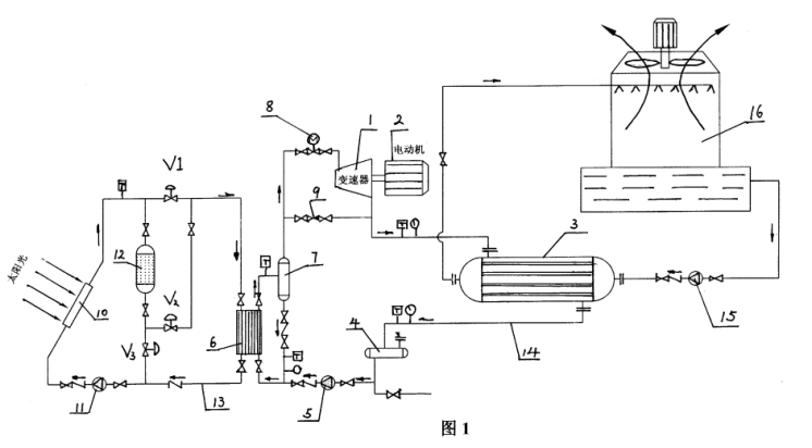
Main configurations for specific implementation:
Organic turbine (or expander) 1,
Excitation AC generator 2,
Air-cooled condenser 3,
Working fluid reservoir 4,
Working fluid booster pump 5,
Plate heat exchanger 6,
Vapor-liquid separator 7,
Steam inlet regulating device 8,
Emergency pressure relief device 9,
Solar vacuum tube collector heater 10,
EVP hot oil (water) liquid ring vacuum pump/dry vacuum pump 11,
Solar heat storage tank 12,
Solar hot oil (water) circulation pipe 13,
Copper pipe 14,
EVP cooling water liquid ring vacuum pump/dry vacuum pump 15,
Cooling tower 16

The solar thermal oil (water) circulation pipe 13 is connected from the bottom of the heat storage tank 12, connected to the inlet of the EVP liquid ring vacuum pump 11, and then connected to the inlet of the solar heater 10. The heated hot oil (water) is connected to the upper part of the heat storage tank 12 and the inlet position of the plate heat exchanger 6 by a pipeline. The electric control valves V1, V2, and V3 are set on the oil (water) pipeline, which can realize the conversion function of using the heat storage tank 12 to store heat and heat the heat medium oil (water).
The intermediate heat medium oil (water) is connected from the lower part of the heat storage tank 12 to the plate heat exchanger 6, and the heat is transferred to the circulating working medium in the thermodynamic power generation circuit in the plate heat exchanger. The cooled heat medium oil (water) is pressurized by the EVP liquid ring vacuum pump 11 and sent back to the solar collector for heating.
EVP high-performance liquid circulation vacuum pump or dry screw vacuum pump:
EVP liquid ring vacuum pump reference picture:

Dry Screw Vacuum Pump Pictures:

The circulating working medium steam generated by the plate heat exchanger 6 flows into the vapor-liquid separator 7, the liquid is separated and heated and vaporized by the plate heat exchanger 6 again, the dry steam is introduced into the turbine (or expander) 1 along the main steam pipe to expand and work, driving the generator 2 to work and generate electricity, the low-pressure steam after expansion and work is transported to the air-cooled condenser 3 by the exhaust pipe to condense into liquid, and then flows into the working medium reservoir 4, and then is sucked and pressurized by the working medium booster pump 5 to become a high-pressure liquid under the evaporation pressure, and is sent to the plate heat exchanger 6 through the pipeline to be heated and evaporated by the hot oil (water) of the solar energy, completing a cycle.
The water cooled by the cooling tower 16 is stored in the water collection tank, connected to the cooling water circulation pump 15 by a pipeline, and is pressurized by the pump to the water condenser, and the hot water after absorbing the condensation heat of the working medium is sent to the water distribution pipe inlet of the cooling tower 16 by a pipeline again.
Kunming built a low-temperature solar thermal power generation prototype with a capacity of 3KW. According to thermal calculations, 870 58U vacuum tubes (d58x2100) solar thermal collector heaters were installed on the roof (calculated based on a heat collection intensity of 600-700w/m2). The intermediate heat medium is water, the volume of the solar thermal storage tank is 3.5m3, the collector water outlet temperature is 93℃, the return water temperature is 83℃, the solar hot water circulation pipe and the intermediate heat medium pipeline are insulated with 50mm thick foamed rubber-plastic pipe shells, and the intermediate heat medium water and power circulation are connected. Plate heat exchangers are used between the working fluids, and Pentane (C5H12) is used as the working fluid for the power cycle. The working fluid circulation loop uses copper tubes d12x1. The working fluid copper tubes between the heat exchanger and the turbine are insulated with 50mm thick foamed rubber and plastic tube shells. The working fluid booster pump uses a shielded pump with a flow rate of 1500kg/h and a discharge pressure of 0.4MPa. It uses a water-cooled condenser and is equipped with a mechanical ventilation cooling tower. The EVP high-performance water circulation vacuum pump uses a pipeline pump, a special screw expansion power machine and an excitation generator.
For more details about vacuum pumps and vacuum systems in power plant processes, please consult the EVP Vacuum Team.