
turbo molecular pump working principle
Molecular pumps use high-speed rotating impellers to transfer momentum to gas molecules, so that the gas produces directional flow and pumps the vacuum pump. Turbomolecular pump has the advantages of fast start-up, anti-radiation, anti-atmospheric shock, no gas storage and desorption effect, no oil vapor pollution or little pollution, and can obtain clean ultra-high vacuum. Turbomolecular pumps are widely used in high-energy accelerators, controllable thermonuclear reaction devices, heavy particle accelerators and advanced electronic devices.
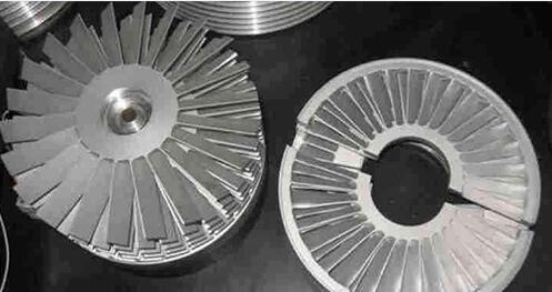
Fig.: turbo molecular pump dynamic and static blade diagram
Turbo molecular pump structure and working principle
In 1958, W. Baker of the Federal Republic of Germany first proposed a practical turbomolecular pump. Since then, various kinds of molecular pumps with different structures have appeared, mainly vertical and horizontal. Fig. 1 is the structure diagram of the vertical turbomolecular pump. Turbomolecular pump is mainly composed of pump body, rotor with blade (i.e. moving impeller), static impeller and drive system. The linear velocity of the outer edge of the moving impeller is as high as the speed of the thermal movement of the gas molecules (usually 150~400 M / sec). The compression ratio of a single impeller is very small, and the turbo molecular pump is composed of more than 10 moving impeller and static impeller. The impeller and the static impeller are arranged alternately. The dynamic and static impeller size is basically the same, but the blade inclination angle is the opposite. The integral rotor composed of 20 moving impellers. A stationary impeller is installed between every two impellers. The outer edge of the static impeller is fixed by a ring and the clearance between the dynamic impeller and the static impeller is about 1 mm. The dynamic impeller can rotate freely between the static impeller and the static impeller.
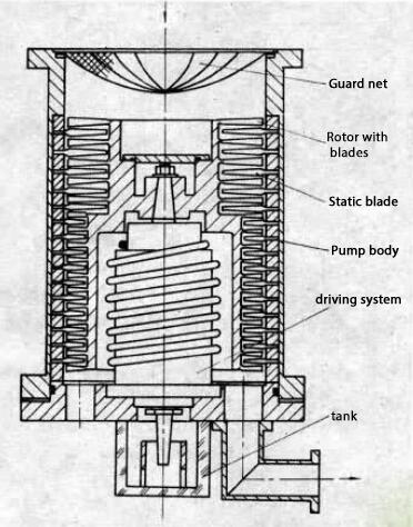
Fig. 1: vertical turbine molecular pump structure diagram
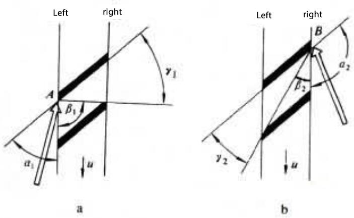
Fig. 3: molecular pump blades schematic diagram
Fig. 3 is a schematic diagram of a moving blade of a molecular pump. The gas molecules on both sides of the moving blade diffuse diffuse. On the left side of the impeller (Fig. 3a), when the gas molecule reaches point A, the gas molecule reflected in angle alpha 1 returns to the left side; one part of the gas molecule reflected in angle beta 1 returns to the left side, the other part crosses the blade to the right side; and the gas molecule reflected in angle gamma 1 will directly pass through the blade to the right side. Similarly, on the right side of the impeller (Fig. 3b), when the gas molecule is incident near point B, the gas molecule reflected in the angle of alpha 2 will return to the right side; one part of the gas molecule reflected in the angle of beta 2 will reach the left side, the other part will return to the right side; and the gas molecule reflected in the angle of gamma 2 will pass through the blade to the left side. The motion of the inclined blade causes the gas molecules to cross the blade from the left to the right, which is much more likely to cross the blade from the right to the left. When the impeller rotates continuously, the gas molecules continuously flow from the left side to the right side, resulting in the pumping action.
Performance and characteristics of turbo molecular pump
The ratio of pump exhaust pressure to intake pressure is called compression ratio. The compression ratio is related not only to the series and rotational speed of the pump, but also to the type of gas. A high molecular weight gas has a high compression ratio. The compression ratio for nitrogen (or air) is 108-109; for hydrogen 102-104; and for gases with large molecular weight such as oil vapor, it is greater than 1010. The limit vacuum of the pump is 10-9 Pa, the working pressure range is 10-1-10-8 Pa, and the pumping rate is tens to thousands of liters per second (1 liter = 10-3 meters). Turbomolecular pump must work in the molecular flow state (the average free path of gas molecules is much larger than the maximum size of the duct cross section) to show its superiority. Therefore, it is required to equip a front-stage vacuum pump with working pressure of 1-10-2 Pa. The molecular pump itself is driven directly by an intermediate frequency motor with a rotational speed of 10000~60000 R / s.
If you want to know more about our vacuum pump products, or if you want to consult vacuum pump materials, please leave a message or send an email to contact@evpvacuum.com.